Common feature of Vacuum Compatible Stage
Introduction
| 'Kohzu vacuum-compatible stages' are precise and durable positioning instruments ideally suited for the extreme requirements imposed by high-vacuum environments. Our vacuum-compatible stages exhibit performance characteristics comparable to those of Kohzu standard motion products. Kohzu vacuum-compatible stages are manufactured, assembled, inspected and packaged under highly controlled conditions. Since proper selection is at the core of vacuum-compatibility, Kohzu engineers only specify low outgas metals, plastics, lubricants and components... materials are limited to aluminum, stainless steel, and phosphor bronze. Kohzu's years of developing customized vacuum-compatible solutions for synchrotron radiation research, semiconductor lithography and space development applications have yielded a vacuum-compatible motion instruments product line of unsurpassed quality, reliability and performance. Ultra high vacuum oil-free lubrication as well as high-precision linear and angular encoders can be provided on request. Please feel free to contact us for all your high and ultrahigh vacuum needs. |
Vacuum Test Results
| • Ultimate System Pressure • Residual Gas Analysis • Outgas Rate A small chamber was prepared to conduct these three vacuum tests. Vacuum chamber is first tested empty before introducing Kohzu's MVSA07A-RT vacuum-compatible swivel stage. |
■ Test Equipment |
*1. Kohzu 70mm stage, Medium Vacuum Compatible *2. Seiko Seiki SPT-400 *3. Anesto Iwata ISP-250B *4. Anelva MG-2F with MIG-430 Controller *5. Anelva M100QA-M,2.5mA filament current,1400V induced voltage at 2nd electron multiplier. |
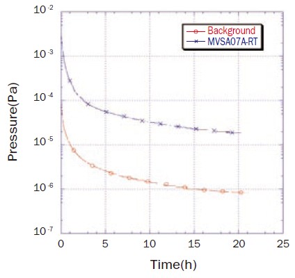
1.Ultimate System Pressure
Fig. 1 Pressure vs. Time (Click enlarge the picture) |
 |
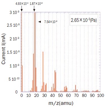
2.Residual Gas Analysis
| Quadrupole mass spectrometer detects mass to charge ratio (m/z), where most elements detected are hydrogen, water, carbon and nitrogen compounds. Additionally traceamounts of hydrocarbon and carbonate fluorine are detected and directly attributed to the vacuum grease used to lubricate our stages. The partial pressures of trace contaminants represent a small contribution to overall system pressure. However, outgassed contaminants will increase as stage temperature rises. If ultra high vacuum conditions are required, we offer customized oil-free stages fitted with materials and lubricants suitable for baking. Kohzu can address all of your vacuum requirements, including those for UHV motion applications. |
 |
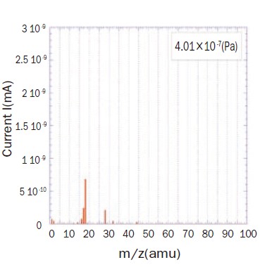 |
Fig. 2 After introducing stage (no baking) and After baking chamber for 10hrs. at 150°C (without stage) |
| Sample Stage(Click enlarge the picture) | Back Ground (without sample stage) (Click enlarge the picture) |
3.Gas Emission Velocity (Orifice method)
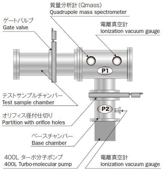 |
A partition is installed between the test sample chamber P1 and base chamber P2 that is connected to the exhaust system. The partition has fine holes that generate a pressure difference between P1 and P2. By measuring the pressure of P1 and P2 and examining the pressure difference, the gas emission velocity from the sample can be obtained. Since emission and adsorption occur also on the surface of the vacuum equipment, first perform measurements with empty chambers for control data. Calculate the net gas emission velocity from the sample by subtracting the control data. (Click enlarge the picture) |
Q=C{(P1-P2)-ground}(Pa・m3/sec) |
How to use in vacuum
●Vacuum Chamber
Consideration must be given to vacuum vessel volume, content outgas rate and the system's pumping conductance. |
●Vacuum Handling
Minimize exposure of vacuum-compatible stages to atmo-spheric conditions. After unpacking, install vacuum-compatible stages into a vacuum chamber as soon as possible. |
●Motor Heating
Heat conductivity and dissipation are significantly reduced in a vacuum environment. This will lead to over-heating of in-vacuum stepper motors if operated continuously for long periods of time. Motor overheating will lead to a rise in system pressure caused by the evaporation of motor-bearing lubricants. Evaporation of motor-bearing lubricants can in turn lead to premature bearing failure. |
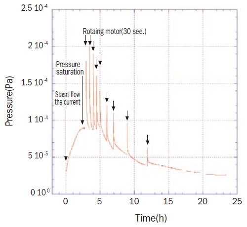 |
The left graph shows pressure change over time as an in-vacuum stepper motor is powered 'On' and 'Off' inside a vacuum chamber. According to the data collected, after starting a current flow to an in-vacuum motor, system pressure will increase until reaching a saturation point. If the motor generates in every 30 seconds, the pressure level is getting higher immediately, but after that, the pressure returns to lower level. By repeating the motor running, the pressure is going down a gradually. |
| Fig. 3 Pressure vs. Time (while cycling motor) (Click enlarge the picture) |
●To improve or maintain minimum system pressure...
1.Running in-vacuum motors as previously described |
●To improve or maintain maximum positional accuracy...
1. Reduce motor heating by minimizing power 'On' cycles and holding current. Or, install thermal insulation between motor and motion mechanics |