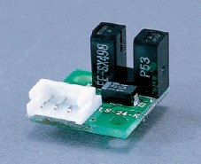
Photosensor Circuit Board
Photosensor (limit, index, home)
| Motorized stages are typically equipped with photo sensors: limit sensors, index sensor, and home sensor. (Note that some stages are not equipped with index sensor.). The limit sensor is mounted on the stage end to limit its motion range *1. The home sensor and the index sensor are mounted on the center of stage and on the motor shaft to reproduce the original position of the stage. |
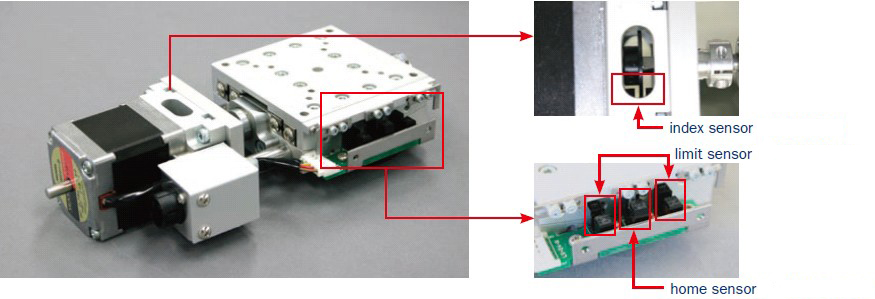
| *1 If the stage is moved beyond the specified stroke, collision of parts may occur, resulting in breakage. Be careful when changing the stroke of the limit sensor. |
Photosensor installed as limit detection and Home position sensors are in conformity with our controller standards. However, the logic of the sensor output can be changed so as to meet the controller specifications on the user side. Please select a photosensor circuit board which meets wiring specifications for the stage to be used. |
Select photosensor types
Photosensor circuit board is categorized 15 kinds by logic and shape of photosensor as following list. When sensor output changing
is necessary, check the "Sensor Type" of specification of using stage in each specification of the stage. Then chose the suitable
circuit board from following list. |
All limit sensors are set to normally closed *2. If the sensor logic needs to be changed, we can change it for profit (we can change it free on the purchase). For changes of the logic of photo sensors, see the detailed pages for each stage and M-020 Appendix.
The homing motion that uses the home sensor and the index sensor can be changed to The homing motion with area sensor (datum). This modification is not available for some models.
*2 "Normally closed" means the logic in which the terminals are electrically continuous in their normal operation state.
List of Photosensor Circuit Board
| Image | Model | Power voltage |
Sensor output (when light is shielded) |
Photosensor | Price (JPY) |
Qty | RFQ | ||
| S1 | S2 | S3 | |||||||
| F-101 | 12VDC, 24VDC | H | L | H | EE-SX398 EE-SX498×2 |
ASK | |||
| F-102 | 12VDC, 24VDC | L | L | L | EE-SX398×3 | ASK | |||
| F-103 | 12VDC, 24VDC | H | H | H | EE-SX498×3 | ASK | |||
| F-104 | 12VDC, 24VDC | H | - | - | EE-SX498 | ASK | |||
| F-105 | 12VDC, 24VDC | L | - | - | EE-SX398 | ASK | |||
| F-106 | 5VDC, 12VDC, 24VDC | H | H | H | EE-SX4320x3 | ASK | |||
| F-106R | 5VDC, 12VDC, 24VDC | H | H | H | EE-SX4320x3 | ASK | |||
| F-107 | 12VDC, 24VDC | H | - | - | EE-SX498 | ASK | |||
| F-108 | 12VDC, 24VDC | L | - | - | EE-SX398 | ASK | |||
| F-113 | 12VDC, 24VDC | H | - | - | EE-SX4320 | ASK | |||
| F-115 | 5VDC, 12VDC, 24VDC | H | H | H | EE-SX4320x3 | ASK | |||
| F-115R | 5VDC, 12VDC, 24VDC | H | H | H | EE-SX4320x3 | ASK | |||
| F-116 | 5VDC, 12VDC, 24VDC | H | H | H | EE-SX4320x3 | ASK | |||
| F-116R | 5VDC, 12VDC, 24VDC | H | H | H | EE-SX4320x3 | ASK | |||
| PM-L25 | 5VDC, 12VDC, 24VDC | L | - | - | PM-L25 | ASK | |||
PM-L25 is made by PanasonicDevice SUNX.
The sensor output in the above table shows outputs when shielded from light. Note that some of the position detections (CW-LS, CCW-LS and origin position) become effective when shielded from light by the detecting plate, and others become effective when receiving light. |
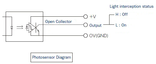
Photosensor Diagram(EE-SX398,EE-SX498,EE-SX4134,EX-SX4320)
Photosensor Specifications Excerpt
| EE-SX398 EE-SX498 |
EE-SX4134 EX-SX4320 |
|
| Output voltage max V out | 28V | 17V |
| Output current max I out | 16mA | 8mA |
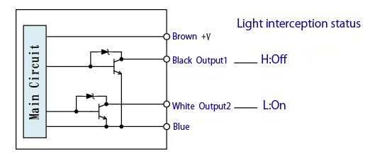
Photosensor Diagram (PM-L25)
Photosensor Specifications Excerpt
| PM-L25 | |
| Output voltage max V out | 30V |
| Output current max I out | 50mA |
PM-L25 is made by Panasonic Device SUNX.
Photosensor Circuit Board
- Precision Positioning Stages
- Vacuum Stages
- Compact 6-Axes Manipulator
- Laser measurement system
- Blur Vibration Simulator
- System Products / Experimental
- Custom-made units
- Product Comparing
- Control Electronics
- Accessories