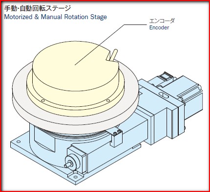
An encoder (shown in the below figure) is used for precision inspections of the accumulated lead error, lost motion, angle repeatability, and pitch error of motorized rotary stage (θstage).
|
 |
< Accumulated Lead Error >
An error as shown in the below diagram appears in an interval of one worm wheel rotation (360°).
Accumulated Lead Error = △L |
 |
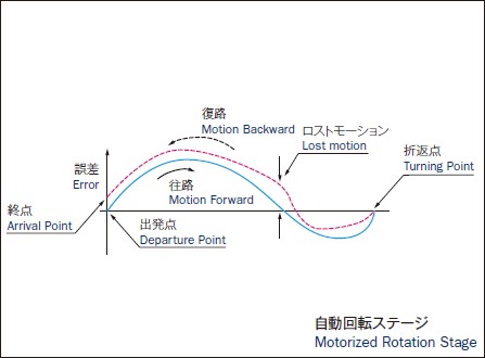
< Lost Motion >
When moving rotation stage from 0° to 360° or vice versa, maximum error between motion forward and motion backward is defined as lost motion.
* The definition of lost motion is difference to X linear stage's.
* The definition of lost motion of tangent- bar lead mechanism motorized rotation stage is same as motorized swivel stage. |
 |
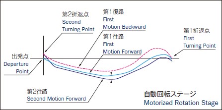
< Angular Repeatability >
The angular repeatability is defined as the maximum difference (regardless of the direction) when a rotation stage rotates twice of full turns of CW and CCW direction. The difference is calculated by comparing actual positioning in each angle from the first and second same directional rotation, and a bigger difference from CW and CCW rotations is defined as the maximum difference and same as the angular repeatability.
* The definition of angular repeatability of tangent-bar lead mechanism motorized rotation stage is same as motorized swivel stage. |
 |
< Pitch Error >
Speed reduction ratio in the worm wheel used for our rotation stage is basically 1 / 180. This means that the gear has 180 teeth at the circumference. This defines the extent of deviation from the standard 2° 00' 00'' for each tooth. |
 |
< Surface Runout>
An indicator is placed into contact in the vicinity of external periphery of the table, and a measurement is made at 36 points for every 10°.
Maximum error ( peak to peak ) is obtained. This value is the sum of deviations resulting from surface runout errors and that derive from finished table surface irregularities.
* The surface runout of tangent-bar lead mechanism rotation Stage is measured in full stroke
angular range. |
 |
< Eccentricity>
The inner diameter as a reference is provided in the main shaft. During final assembly, displacement of this inner diameter is measured with an indicator. This value is the sum of roundness deviations of the inner diameter and eccentricity, and we define this value as eccentricity (only for Mont-Blanc series).
* The eccentricity of tangent-bar lead mechanism rotation stage is measured in full stroke angular range. |
 |