Understanging Motorized XYθ Stage
Understanding Specifications
 |
| YRA-070 |
| Specifications | Description | ||
| Model Number | YRA-070 | Model Number | |
| Table Size | 70mm×70mm | Table size refers to the stage's valid mounting table size. | |
| Guide Mechanism | XY:Cross-Roller Guide θ:Cross-Roller Bearing |
Type of guide mechanism used on this stage. | |
| Motion Range | XY:±3mm θ:±3° | Stage travel range in the positive and negative directions from it's centered or neutral position. | |
| Lead Mechanism | Ball Screw, Lead 1.0mm | Feeding Mechanism and lead screw pitch. | |
| Resolution Full/Half Step | XY:2μm/1μm θ: ≈0.002546°/0.001273° |
Variation of the stage resolution which is defined by microstep division. | |
| Maximum Speed | XY:10mm/sec : Half 10kpps θ:12.7°/sec : Half 10kpps |
Maximum Speed of standard stage (half step, 10kpps). | |
| Lost Motion | X:≦ 2μm(AVE. 0.356μm) Y:≦ 2μm(AVE. 0.354μm) θ:≦ 0.005°(AVE. 0.0013°) |
The difference between the locating point in the + direction and the locating point in the - direction. | |
| Straightness | Horizontal | X:≦ 1μm/6mm(AVE. 0.237μm/6mm) Y:≦ 1μm/6mm(AVE. 0.253μm/6mm) |
Straightness is measured relative to mounting surface |
| Vertical | X:≦ 1μm/6mm(AVE. 0.154μm/6mm) Y:≦ 1μm/6mm(AVE. 0.187μm/6mm) |
||
| Repeatability | X:≦±0.5μm(AVE. ±0.088μm) Y:≦±0.5μm(AVE. ±0.075μm) |
Half of the maximum difference when placed at the measurement point 7times from the same direction. | |
| Angular Repeatability | θ:≦ 0.001°(AVE. 0.0002°) | The maximum value of the difference between the first and second rotation at each positioning point | |
| Backlash | X:≦ 1μm(AVE. 0.35μm) Y:≦ 1μm(AVE. 0.288μm) θ:≦ 0.005°(AVE. 0.0013°) |
The difference between "reference position" and "After applying a load in the feed direction, when no load is applied". | |
| Surface Runout | θ:≦5μm/±3°(AVE. 2.708μm/±3°) | Vertical displacement near the periphery of the table during rotation. | |
| Eccentricity | θ:≦3μm/±3°(AVE. 0.517μm/±3°) | Horizontal displacement of the rotation axis | |
| Moment Load Stiffness | 0.31 arcsec/N・cm | Inclination angle of the stage when the stage is subjected to a moment load | |
| Load Capacity (Horizontal) | 49N (5kgf) | Maximum load capacity is for a horizontally orientated stage with load centered on top-plate. | |
| Material | Aluminum Alloy | Material specification is for stage's main body components only. | |
| Finish | Clear-Matt Anodizing | Surface finish type and color. | |
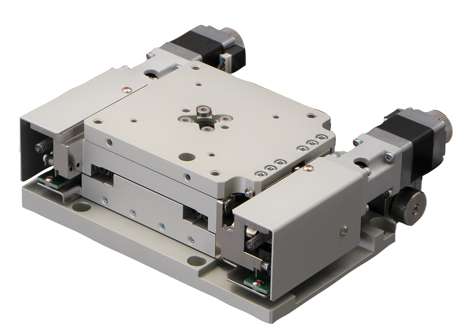
| Weight | 1.7kg | Stage weight includes all components depicted in product photograph. | |
| Motor | PK513PB (Oriental Motor: Phase Current 0.35A, Basic Step Angle 0.72°, 5-Leads) | Motor type of standard stage. | |
| Connector | 20Pin Round (Hirose: RP13A-12JG-20PC) | Connector type of standard stage. | |
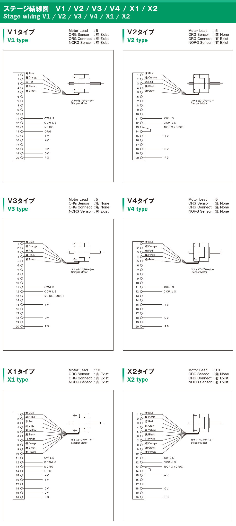
| Stage Wiring Type | V3 | Wiring type is connection between stage and stepper motor, and photo-sensor. | |
| Sensor Model | XY:F-106(HOME, LIMIT), θ:F-106R(HOME, LIMIT) | Sensor circuit Board | |
| Price (JPY) | ¥450,000 | Catalog price in Japanese currency. | |
| Lubricant Change(JPY) | ¥45,000 | Lubricant replacement cost | |
| Motor Change(JPY) | Same size ¥45,000 different size ― |
Motor replacement cost | |
| Overhaul Price(JPY) | ¥120,000 | Overhaul price ※ | |
Additional parts cost is not included on Overhaul cost.
Guide Mechanism Type
●Cross-Roller Guide
| In cross-roller guides, quench hardened and precision ground bearing surfaces move upon loose hardened steel cylinders (rollers) with rotation axes oriented in alternating 90 degree angles (Ref. Fig.1). Having rollers arranged in an alternating cross pattern allows preloading and operation at any angle. The roller bearings are held apart from one another by a bearing cage, which prevents adjacent rollers from touching. Since cross roller bearings have little difference between static and dynamic friction they minimize start-to-stop slip-motion typical of other bearing types. The line contact of roller bearings along with precise roller-to-race gap management provide larger load-bearing surfaces, higher preloads and meet very tight runout and stiffness specifications. | 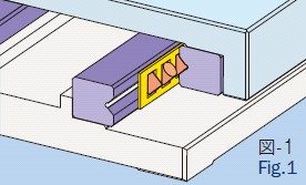 |
●Cross-Roller Bearing
| In cross-roller bearing, quench hardened and precision ground bearing surfaces move upon loose hardened steel cylinders (rollers) with rotation axes oriented in alternating 90 degree angles (Ref. Fig.1). Having rollers arranged in an alternating cross pattern allows preloading and operation at any angle. The roller bearings are held apart from one another by a bearing cage, which prevents adjacent rollers from touching. Since cross-roller bearings have little difference between static and dynamic friction they minimize start-to-stop slip-motion typical of other bearing types. The line contact of roller bearings along with precise roller-to-race gap management provide larger load-bearing surfaces, higher preloads and meet very tight run out and stiffness specifications. | 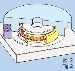 |
Feeding Mechanism
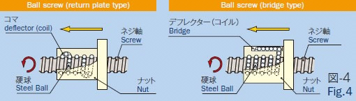
●Ball Screw
| The ball screw consists of a screw spindle, a nut, and steel ball between them (Fig. 4). When the screw is rotated, the ball rolls and moves between the ball screw and the nut, and then returns to its original position. Since a ball is rolled, the friction is low, a high transmission efficiency is obtained, the difference between static friction and dynamic friction is small, and stick-slip does not easily occur. |
 |
Resolution of XY stage
| Resolution of XY stage is calculated based on the following formula. |
ΔX = (p・Δθ/ 360m )
|
| * Kohzu uses two motors with basic step angles of 0.36° / pulse and 0.72° / pulse, and a feed screw pitch of 0.5 to 5mm/rev. The resolution described in this catalog is calculated with two (2) divisions of the standard motor step (half- step, where the value of m is 2). |
Resolution of tangent-bar style stage
| Resolution of tangent-bar style stage is calculated based on the formula below. |
Δθs =tan-1 (Δθ・P / 360・R・m) |
Reference material:Length of the tangent bar
| Model Number | R (mm) |
| YRA-070 | 45 |
| YRA-071 | 45 |
| YRA-130 | 85 |
| YRA-200 | 115 |