Understanding Vertical Linear Stage Specifications
Understanding Specifications
 |
| ZM07A-S3K |
| Specifications | Description | |
| Model Number | ZM07A-S3K | 1. Kohzu's significant alpha-numeric model numbers offer quick product insight. |
| Mirror Model Number | ZM07A-S3K-R | 2. Mirror symmetry of standard stage |
| Table Size | 70mm x 70mm | 3. Table size refers to the stage's valid mounting table size. |
| Guide Mechanism | Cross-Roller Guide | 4. Type of guide mechanism used on this stage. |
| Motion Range | Coarse ±3mm, Fine 0.15mm | 5. Stage travel range in the positive and negative directions from it's centered or neutral position. |
| Vertically | ≦4μm/6mm | 6. Vertically is measured relative to mounting surface |
| Minimum Readout | Coarse 5μm/Scale, Fine 0.25μm/Scale | 7. Minimum readout is the smallest measurable actuator motion increment. |
| Load Capacity (Horizontal) | 29.4N(3kgf) | 8. Maximum load capacity is for a horizontally orientated stage with load centered on top-plate. |
| Material | Aluminum Alloy | 9. Material specification is for stage's main body components only. |
| Finish | Clear-Matt Anodizing | 10. Surface finish type and color. |
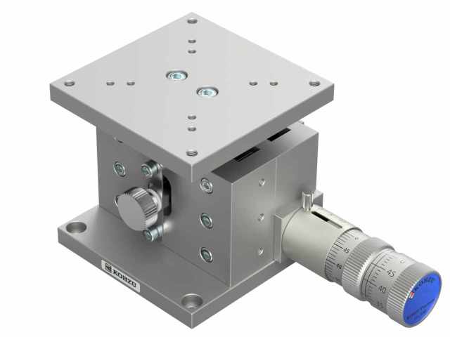
| Weight | 0.9kg | 11. Stage weight includes all components depicted in product photograph. |
| Actuator | Fine Pitch Positioner FPP03-13 (13mm) | 12. Actuator model number and travel range. |
| Price(JPY) | ¥116,000 | 13. Catalog price in Japanese currency. |
| Overhaul Price * | ¥24,000 ~ | 14. Overhaul price in Japanese currency |
| Clean Room Lubricant Change Price | ¥18,000 | 15. Clean Room Lubricant change Price in Japanese currency. |
| Vacuum Lubricant Change Price | ¥18,000 | 16. Vacuum Lubricant change Price in Japanese currency. |
* Parts price is not included overhaul price.
* Micrometer is exempt overhaul.
Guide Mechanism Type
●Cross-Roller Bearing Guides
| The cross-roller guide is a limited stroke linear and bending guide that consists of a roller race and rollers. The roller race has 90 degree V-shape surface and it is harden and precisely polished. It is not only had a polished precise surface but also precisely correct 90 degree. The cylindrical shaped rollers are inserted between two roller races and they are aligned alternately. When the stage is moved, these rollers are rolling smoothly at the same time with the same tension because the gap between roller race is correctly arranged and maintained for the same distance. There is no slipping, no stopping due to the effective contact. As one of the feature, it has highly rigid more than ball guide because it has a longer contact line. |
●Wedge Type Cross-Roller Guides
| One set of wedge type cross-roller guides are mounted on the horizontal plane and the other set of guides are tilted so that tangent is 1/4 (approximately 14°) (see Fig. 1). If the wedge is pushed in from one side, the table fixed to the central axis moves vertically. Since the tilted cross roller guide supports the horizontal component of force, the moment load rigidity on the table top face is reinforced (same as 1/2 type). | 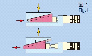 |
●Gothic Arc
| Gothic arc is guide mechanism that is consist from the pseudo-cylindrical sliding surface and the ball (see fig-2). This sliding surface is processed into both of table and base of the stage, and finish in quench and grind. The ball is set between groove of sliding surface. The sliding surface touch the ball in each 4 point, then this point contact mechanism not likely to bring up differential slip. And the size of ball is used for pressurizing control, it bring decreasing of parts number. | 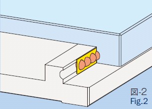 |
Feeding Mechanism
●Micrometer and Lever
| This system converts the horizontal force of the micrometer head to a vertical force and moves the stage vertically by means of a lever (see Fig.3). The basic structure is the same for all types and two actuators, the micrometer head and fine pitch positioner are available. | 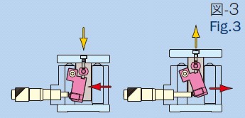 |
●Wedge type cross-roller guides
| This system converts the horizontal force of the micrometer head to a vertical force by means of a 1/4-wedge and moves the stage vertically (see Fig. 1 on the previous page). The basic structure is the same for all types and two actuators, direct connection of the handle-wheel rotation to the driving ground screw and a fine pitch positioner for pushing the wedge, are available. |
Travel Distance
| * The following type stage, the micrometer measurement display matches the actuator movement distance. With other stages, the display may not accurately match the actual movement distance. |
●Micromete and Lever
| The force that is generated by pushing with the micrometer head is converted to a vertical force by means of a lever (see Fig.3). The precise movement distance is indicated by a function of distances from the fulcrum of the lever to the power point and to the action point, and by the shape of the micrometer head tip. The vertical movement distance is approximately 1/2 of the micrometer head movement distance. |
●Wedge Type Cross-Roller Guides
| The upper stage moves vertically by either of two means: the ground screw that is directly connected to the handle or by inserting a wedge to the fine pitch positioner (see Fig. 1 on the previous page). Since the vertical-to-horizontal ratio of the wedge is 1:4, the vertical movement distance is 1/4 of the wedge push-in depth. For the handle-wheel type, one rotation corresponds to 0.125 mm and one division of the scale corresponds to 5 μm of movement. For the fine pitch positioner type, coarse adjustment can be made in 2.5 mm increments and fine adjustment in 0.125 μm increments. |
Vertical (Z-type) Configuration
| Typically, to suppress any influence from the stage top face, the feed mechanism is mounted on the base of stage. If the stand type is used with this mounting configuration, a load is applied along the spring extension of the stage and the stage may drop due to gravity (as shown in the left part in the right figure). Bracket type vertical linear stage may solve this problem by changing the position of micrometer holder.(see the right part in the right figure). | 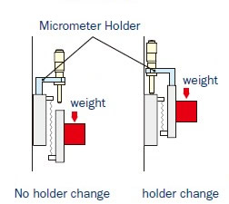 |